")


")
27 channel LED Controller DMX Constant Voltage
27 channel LED Controller | 9 x RGB Zone LED Controller
Ideal for: LED Strips, LED Tape and Sign Lighting Modules.
Great value 27 Channel LED Controller!
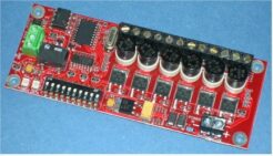
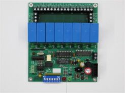
The DMX-9 is a multi channel 27 channel or 9 x RGB Zone led dimmer system designed to control voltage driven, Common Anode LED lighting systems comprising either RGB or separate single colour systems, giving up to a total of 27 individual colour channels. Popular with led installers and signmakers requiring multi-channel control of LED Strips, LED Tape and Sign Lighting Modules, 12V or 24V.
DMX9 has 3 electrical interfaces available on the system to allow a wide range of end user applications and some in-built programs. DMX interface is fitted as standard, but USB or RS232 can also be provided. 5A/channel, max. 25Amps per card.
This 27 Channel LED Controller is for common anode led systems with constant voltage led fixtures and led sources.
Order, explore our discounts or get expert DMX hardware advice today:
SKU: MLE#DMX9CV - A 27 Channel LED Controller.
DMX 9 | Features:
- 27 channel led decoder-driver
- USITT DMX512 / 1990 (4µSec) compliant
- High current fused outputs
- Fully selectable DMX base address
- On-board terminate setting (120 Ohm)
- Full isolation from DMX connection for maximum reliability
- Power and Data indicator LEDs
- Built in stand-alone programs
- Protection against reverse power input
- Custom builds available
DMX 9 | Specifications:
The DMX-9 board is designed to work with Common Anode configured LED systems. As Standard it works with regulated 12 to 24Vdc power inputs, and outputs this to the LED outputs through a dimming control system.
- Maximum output current per colour channel: 5Amps (Fused).
- Maximum total output drive capability: up to 25A total capability.
- Input Power Consumption: 50mA quiescent current at 12Vdc with no LED loading.
- Output frequency: 100Hz approx.
- Dimming levels (all channels): Off and 1 to 255 (0 to 100%)
- Selectable DMX termination impedance: 120W
PCB Dimensions:
Standard FR4 double sided PTH board, 1.6mm thick. 106mm x 138mm size.
Tallest component 20mm above PCB.
Recommended underside clearance 5mm.
Fixing centres on 99mm x 130mm. Fixing hole size 3mm dia.
Recommended maximum screw and pillar outer diameter: 6mm (if metal).
MODES | DMX 9
A. interface Protocols
DMX512: RS485 standard at 250kbps. 8 Data bits, 1 Start bit, 2 Stop bits.
B. RS232: RS232 standard at 19.2kbps. 8 Data bits, 1 Start bit, 1 Stop bit, no Parity.
C. USB
A.USITT DMX512 / 1990 (4µSec) This is an industry standard interface used widely for the control of lighting dimmers. The DMX-9 board is also capable of handling the older version of DMX512 having a 4µ Second ‘Mark After Break’ with no change of setting. Using dip switches, the user can select a start address anywhere between 0 and 511. The user is also able to terminate the DMX512 chain by simply flicking a dip switch – no need for a terminator plug. The integral DMX512 interface includes isolation from the rest of the circuit and mains earth to avoid earth problems.
B. RS232 Interface (Optional Extra) This interface can connect directly to a PC or MAC with an RS232 (serial) port. All the functions DMX can offer are available through this interface along with a few extras. This allows for custom PC or MAC software to be written to perform the required functions, without the expense of a DMX controller. Alternatively an embedded system could also take control of the board.
> In-built Stand Alone Functions By setting high unused DMX addresses, stand-along programs are activated. These programs do not require any external controller and free run from the point of switch on. Also diagnostic functions are available to help quickly solve connection and other problems.
For stand-alone operation, DMX9-27 uses following DMX address functions:  Address 511: All channels on full – useful for checking connections Address 510: Cross fade pattern on all channels Address 509: System check – outputs checksum on LEDs.
DMX Settings | DMX9
Dip Switch Configuration:
The dip switches are located at the front of the board beside the two status LEDs. The switch is a right-angled type, so to be accessible from the outside of a casing through a cut-out window.
The 10 dip switches provide access to all the user settings. These switches are read only on start-up, so any changes made while the board is powered will require a power down reset to take effect. Switch functions are given below:
SW1: DMX address bit 0 [ = 1].
SW2: DMX address bit 1 [ = 2].
SW3: DMX address bit 2 [ = 4].
SW4: DMX address bit 3 [ = 8].
SW5: DMX address bit 4 [ = 16].
SW6: DMX address bit 5 [ = 32].
SW7: DMX address bit 6 [ = 64].
SW8: DMX address bit 7 [ = 128].
SW9: DMX address bit 8 [ = 256].
SW10: DMX Terminate (on or off). Changing this switch does not require reset.
Note: Setting a DMX start address of 0 (switches 1..9 off) is invalid for DMX and will invoke RS232 mode. Any non zero setting of Switches 1..9 will set the base address of the board for DMX mode, such that output channel 1 will respond to data at the base address, output 2 respond to data at base address +1 and so on.
For stand-alone use the following table shows the high DMX addresses functions:
> Address 511: All channels on full – useful for checking connections
> Address 510: Cross fade pattern on all channels
> Address 509: System check – outputs checksum on LEDs.