LED Light Guides and LED Edge Lighting pt2
SOURCE: Agilent Technologies

<< View LED Light Guides and Edge Lighting part 1
[ezcol_2third]
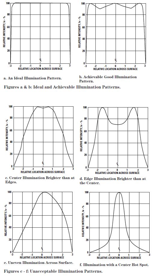
Figure 24. Illumination Patterns of Various Light Guide/Diffusing Film Combinations.
[/ezcol_2third]
[ezcol_1third_end]
These same concepts may be
applied to making small sized
annunciators utilizing the light
pipes described in the following
section. In many cases, silkscreening
an opaque background,
leaving open letters or a symbol, is
most effective. The silk-screened
diffusing film is glued to the exit
surface of the light pipe with an
optically clear adhesive to form the
annunciator module. In the “off”
condition, the letters or symbol are
dark and without color and tend to
blend with the background. In the
“on” condition, the bright letters or
symbol, with the color of the LED
light, stand out vividly contrasting
in appearance against the
background.
[/ezcol_1third_end]
[ezcol_1third]
Simple Shaped Light Pipes for Front Panel Indication
Light guides for front panel
indication are typically called “light
pipes.” Light pipes can be made in
many simple and compound
shapes. Simple cylindrical,
rectangular, and triangular shaped
light pipes are illustrated in Figure
25, utilizing an SMT LED as the
light source. These simple light
pipes can be made from
commercially available plastic rod.
Custom Shaped Light Pipes for Front Panel Indication
Custom shapes, usually precision
molded, are designed to achieve
special effects, as illustrated in
Figure 26. Two or more LED light
sources may be needed to
illuminate a large arrow shaped
light pipe. A “three legged” light
pipe may be used to give a three
condition status in a single
indicator, red for “danger”, yellow
for “caution”, and green for “safe”.
Compound Shaped Light Pipes for Front Panel Indication
Compound light pipe
configurations may also be
precision molded for specialized
applications. The serpentine light
pipe, shown in Figure 27, is
designed to move light around an
obstruction. The light ray
reflections follow the curvature of
the light pipe without loss.
Multiple Element Light Pipe Arrays
Multiple element light pipe arrays
may be molded as a single piece
part. Figure 28a shows a four
element linear light pipe array
molded as a single piece part. The
thickness of the tie plate (or tie
bar) should be sufficient to provide
the necessary level of support for
correct positioning of each light
pipe element. For the assembly
shown, the 0.254 mm (0.010 in.)
[/ezcol_1third]
[ezcol_2third_end]
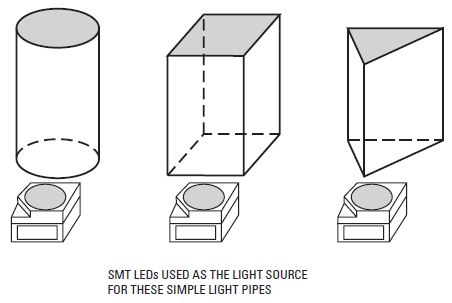
Figure 25. Simple Light Pipe Shapes for Use as Front Panel Indicators Using an SMT LED as the Light Source.
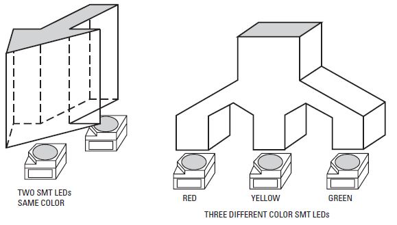
Figure 26. Custom Shaped Light Pipes for Use as Front Panel Indicators.
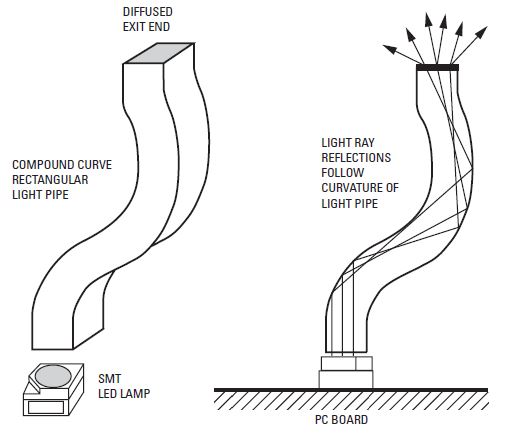
Figure 27. A Serpentine, Rectangular Light Pipe Designed to Move Light Around an Obstruction.
[/ezcol_2third_end]
[ezcol_1third]
thick tie plate is flexible,
permitting manual adjustment of
each light pipe as the array is
installed in the next assembly. The
2.54 mm (0.100 in.) thick tie bar in
Figure 28b is rigid, holding the four
serpentine bar elements in precise
position to assure accurate
placement into the next assembly.
Since the thin tie plate and rigid tie
bar are perpendicular to the light
pipes, cross coupling of scattered
light from an illuminated light pipe
element is minimal, and will not
illuminate adjacent light pipe
elements.
Tinted, Diffused vs. Untinted, Nondiffused LED Lamps as Emitters for Light Pipes
In most cases, untinted,
nondiffused LED lamps with semiwide
flux radiation patterns of 24
degrees, or larger, are preferred
emitters for light guides and light
pipes. However, there are designs
where a tinted, diffused LED lamp
with a wide radiation pattern of 45
to 60 degrees is the preferred
emitter. This concept is illustrated
in Figure 29. The semi-wide
radiation pattern of a T-1 3/4
untinted, nondiffused LED lamp
fits the requirements of a long
“slim” light pipe. However, a short
“stocky” light pipe requires an LED
lamp with a wide flux radiation
pattern to prevent a “hot spotty”
appearance at the exit end that
may be caused by using a lamp
with a narrower radiation pattern.
Molded, Flexible, Diffused, Light Pipe Arrays
Flexible, diffused, light pipe arrays
are very effective in backlighting
keypads and indicator windows in
front panel assemblies. Flexible
light pipe arrays are usually
molded from an untinted, diffused,
optical grade silicone rubber, such
as 150-OU, supplied by Tory
Rubber Company, a division of
Dow Corning. As illustrated in
[/ezcol_1third]
[ezcol_2third_end]
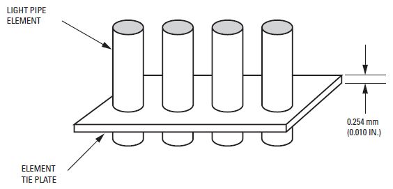
Figure 28a. A Four Element Light Pipe Linear Array, Molded as a Single Piece Part with a Flexible Tie Plate.
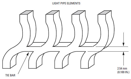
Figure 28b A Four Element Serpentine Light Pipe Linear Array, Molded as a Single Piece Part with a Rigid Tie Bar.
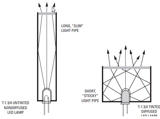
Figure 29. Conceptual Use of Tinted, Diffused and Untinted, Nondiffused LED Lamps as Emitters in Different Light Pipe Configurations.
[/ezcol_2third_end]
[ezcol_1third]
Figure 30a, the individual light pipe
elements are short in length, are
either solid or hollow inside, and
vary in size and shape. The SMT
LED lamps fit up against the bases
of solid light pipe elements, or fit
inside hollow light pipe elements,
as illustrated in Figure 30b. The
light pipe array is placed over an
SMT LED lamp pc board assembly
to form a backlighting unit, as
illustrated in Figure 30b. A bright,
wide angle illumination pattern is
achieved at the exit end of each
light pipe element. A pc board
assembly with standard T-1 3/4 or T-
1 LED lamps may also be used,
with the lamps fitting inside the
hollow elements of the flexible
light pipe array. The backlighting
unit is then mated with the keypad
and front cover to form the
illuminated front panel assembly.
The push button caps in the
keypad are molded from untinted,
nondiffused acrylic or
polycarbonate. The indicator
windows in the front cover are
untinted and usually nondiffused.
Both the key caps and windows
may be diffused if desired. The
wide illumination pattern from
each diffused light pipe element
assures an even illumination and
wide viewing angle for each push
button cap and front panel
indicator window. In some panel
designs, the indicator windows are
cut-outs in the front panel cover,
allowing solid light pipe elements
to protrude about 2.54 mm (0.100
in.). This makes a pleasing design,
adding some depth to a front panel
configuration.
The following company designs
and molds flexible diffused light
pipe arrays for backlighting
[/ezcol_1third]
[ezcol_2third_end]
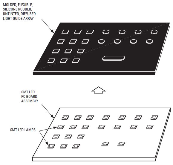
Figure 30a. A Molded, Flexible, Silicone Rubber, Untinted, Diffused Light Pipe Array used in Combination with an SMT LED PC Board.
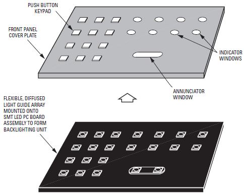
Figure 30b. The Flexible, Diffused Light Pipe Array and SMT LED PC Board Form a Backlighting Unit. This Backlighting Unit Illuminates a Push Button Keypad and Front Panel Assembly.
[/ezcol_2third_end]
[ezcol_1third]
keypads and indicator windows in
front panel assemblies. Diffused
silicone rubber 150-OU is the
material used.
Keytek
44 Old State Road #3
New Milford, CT 06776
(203) 350-1153
FAX: (203) 350-1155
Light Pipe Output Radiation Patterns
The light output radiation pattern
from the exit end of a light pipe
should be designed to meet the
luminance and viewing angle
requirements in a defined ambient
lighting environment. A trade-off is
made between on-axis intensity
and radiation pattern, as illustrated
in Figure 31. A wide radiation
pattern, at the expense of on axis
intensity, Iv (0), is better for a wide
off-axis viewing angle. This is
suitable for most applications in
moderate ambient lighting
conditions less than 1000 fc. For
bright ambient light conditions,
such as for outdoor viewing,
radiation pattern is reduced to
achieve a high on-axis intensity.
A designer may measure the light
output radiation pattern from the
exit end of a light pipe using a
goniometer. The goniometer
rotating detector should be at a
nominal distance of 305 mm (12
in.) from the exit end of the light
guide. Radiation pattern (viewing
angle) curves are obtained, similar
to those shown in Figure 32.
[/ezcol_1third]
[ezcol_2third_end]
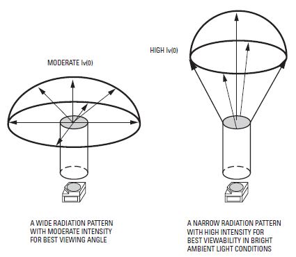
Figure 31. Wide and Narrow Light Pipe Radiation Patterns.
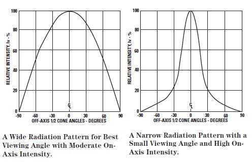
Figure 32. Wide and Narrow Light Pipe Output Radiation Patterns Obtained using a Goniometer.
[/ezcol_2third_end]
[ezcol_1third]
Edge Lighting a Transparent Flat Plate with Grid Lines
A flat transparent plate with
engraved or etched grid lines on
the face surface may be edge
lighted with LED lamps, as shown
in Figure 33a. The face surfaces of
a transparent flat plate are smooth
for an observer to see through. The
surfaces of the grid lines are rough
to give the necessary diffusing
surface. The grid lines may be
coated with a thin layer of white
translucent paint to enhance
daylight readability, with some loss
in grid illumination. All four edges
of the light plate may be painted
with white reflecting paint.
Light within the light plate is
internally reflected by all surfaces,
and escapes only through the
diffused lines providing the grid
line illumination, as shown in
Figure 33b. Holes are drilled into
two opposite ends to accept the
domes of HLMP-650X subminiature
lamps. The LED lamps are epoxied
to the transparent plate and
electrically wired in series. The
rectangular bases of the LED
lamps are not inserted into the
light plate in order to keep the
plate thickness at 2.54 mm (0.100
in.). The number of LED lamps
required, spaced on approximately
1/4 to 1/2 inch centers, is determined
by the size of the light plate and
the desired luminance of the grid
lines.
A transparent plate with engraved
or etched grid lines may also be
edge lighted using surface
mounted SMT LED lamps as
shown in Figure 34. Two surface
mount pc board assemblies are
mounted to the sides of the
transparent plate for even
illumination of the grid lines.
Optional grooves are cut into the
[/ezcol_1third]
[ezcol_2third_end]
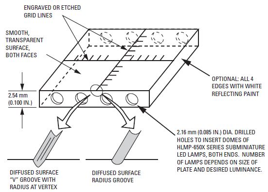
Figure 33a. A Transparent Flat Plate with Engraved or Etched Grid Lines Illuminated by Subminiature LED Lamps, Epoxied to the Plate.
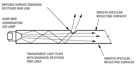
Figure 33b. Internal Reflecting Light Rays Escaping Only Through Engraved or Etched Diffused Grid Lines.
plate to provide alignment of the pc board assembly with the plate. The number of SMT LED lamps, spaced on 1/4 to 1/2 inch centers, depends upon the size of the transparent plate and the required illumination of the grid lines. Advantages of this approach are: 1) the minimum thickness of the transparent plate, typically 2.29 mm (0.090 in.) with optional grooves to enclose the SMT LED lamps, or 2.03 mm (0.080 in.) without grooves for minimal plate thickness, and 2) the LED lamps are not epoxied to the transparent plate.
[/ezcol_2third_end]
[ezcol_1third]
Light Guide Vendors
The following plastic molding
companies offer light guide optical
design assistance and/or can
develop prototypes.
Nitto Jushi Kogyo Co., LTD.
Distributor: Astra Products Inc.
P.O. Box 479, Baldwin, NY 11510
(516) 223-7500 Fax: (516) 868-2371
C-Plastics, 243 T Whitney Street
Leominster, MA 01453
(508) 534-6876 Fax: (508) 537-8238
Lexalite, 10163 US Highway 31 North
P.O. Box 498, Charlevoix, MI 49720
(616) 547-6584 Fax: (616) 547-5833
AO Tech, Division of American Optical
Corp., 14 Mechanics St., P.O. Box 746
Southbridge, MA 01550
(508) 765-9711 Fax: (508) 765-2158
NiOptics Corp. 1801 Maple Ave.
Evanston, IL 60201
(708) 491-2177 Fax: (708) 467-1244
Industrial Devices Inc. (IDI)
260 Railroad Avenue
Hackensack, NJ 07601
(201) 489-8989 Fax: (201) 489-6911
U.S. Precision Lens, 3997 McMann Rd.
Cincinnati, OH 45245
(513) 752-7000 Fax: (513) 752-2841
KHATOD OPTOELECTRONICS
20092 Cinisello Balsamo
(Milan) Italy Via Monfalcone
+39 02 66013695 Fax: +39 02 66013500
MIL-P-7788F LED Lighted Aircraft Panel
Figure 35 illustrates the basic
construction of an acrylic aircraft
LED lighted panel assembly
meeting the requirements of MIL-P-
7788F. This internally lighted panel
uses HLMP-650X untinted,
nondiffused, SMT subminiature
LED lamps surface mounted on a
double sided pc board. Maximum
metalization is used on both sides
to achieve a low thermal resistance
[/ezcol_1third]
[ezcol_2third_end]
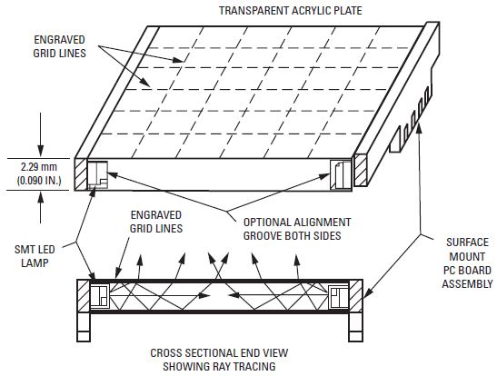
Figure 34. A Transparent Flat Plate with Engraved or Etched Grid Lines Illuminated by SMT LED Lamps on Small Surface Mount PC Board Assemblies.
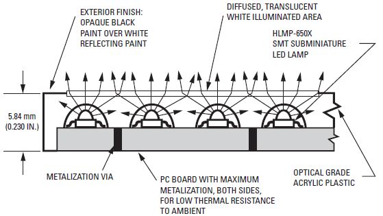
Figure 35. Basic Construction of a MIL-P-7788F LED Lighted Aircraft Panel, Shown in Simplified Cross Section.
to ambient. The LED lamps are distributed throughout the panel to achieve a desired lighting effect. Flux coupling into the panel is 100%. Light rays from the LED lamps blend together within the panel to produce even illumination through the illuminated areas on the face of the panel.
These illuminated areas are diffused and coated with a thin layer of translucent white paint. In daylight, the LED lamps are off, and the illumination areas appear white by reflecting ambient light. At night, these areas are internally illuminated by the LED lamps and appear the same color as the LEDlight.
All exterior surfaces of the panel are painted with a white reflecting paint, leaving open the areas on the face of the panel to be internally illuminated. An overcoat of black, scratch resistant paint is added to form the exterior finish. The overall thickness of the panel is 5.84 mm (0.230 in.).
Coupling an Optical Fiber to an LED Lamp
The most effective method to couple an optical fiber to an LED lamp is to insert the fiber into the lamp package in close proximity to the LED chip. This assures the
[/ezcol_2third_end]
[ezcol_1third]
most efficient flux coupling and
light capture by the optical fiber,
although only a small portion of
the LED emitted flux is actually
captured by the fiber. The
procedure is illustrated in Figure
36a.
1. With a jeweler’s lathe, cut off the top
of the dome package to obtain a flat,
semi-smooth surface.
2. Looking through the flat surface with
a microscope, visually locate one
[/ezcol_1third]
[ezcol_1third]
corner of the LED chip opposite the
wire bond, as shown in Figure 36b.
3. Precision drill an insertion hole down
to the located corner, stopping at a
minimum distance of 0.5 mm (0.020
in.) above the LED chip. Do not come
in contact with the wire bond or LED
chip.
4. With a syringe, insert a clear, room
temperature curing epoxy into the
hole.
5. Immediately insert the optical fiber
[/ezcol_1third]
[ezcol_1third_end]
into the hole with a steady rotary
motion to assure no air bubbles.
6. Let the epoxy cure for the required
length of time.
The optical fiber is now anchored
to the LED lamp package. The flux
emanating from the corner of the
LED chip is captured by the
entrance end of the optical fiber
with minimal loss.
[/ezcol_1third_end]
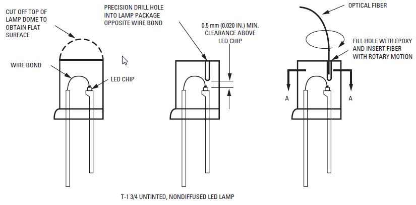
Figure 36a. Technique for Coupling an Optical Fiber to an LED Lamp
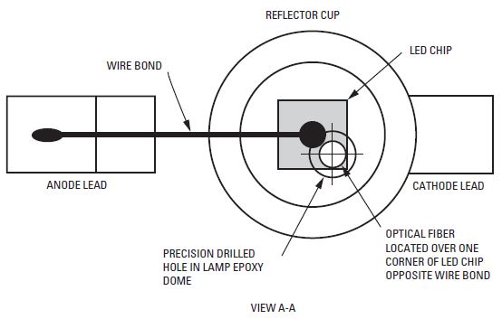
Figure 36b. Positioning of Optical Fiber With Respect to the LED Chip.
List of LED Lamps, Untinted, Nondiffused, Recommended for use in Light Guide Applications
T-1 3/4 LED Lamps
| Part Number | LED and Color | Viewing Angle | Iv, mcd (at 20 mA) Min. | Iv, mcd (at 20 mA)Typ. |
| HLMP-3750 | GaP – 626 nm High Efficiency Red | 24° | 90 | 125 |
| HLMP-3850 | GaP – 585 nm Yellow | 24° | 96 | 140 |
| HLMP-3950 | GaP – 570 nm Green | 24° | 111 | 265 |
| HLMP-C025-P0000 | AS AlInGaP – 625 nm Red | 25° | 500 | 1000 |
| HLMP-C225-O0000 | AS AlInGaP – 590 nm Amber | 25° | 450 | 800 |
| HLMP-C625-P0000 | AS AlInGaP – 637 nm Deep Red | 25° | 500 | 700 |
| HLMP-DB25-P0000 | GaN – 462 nm Blue | 25° | 40 | 100 |
| HLMP-DM25-M0000 | InGaN – 527 nm Green | 25° | 245 | 970 |
| HLMP-DS25-R0000 | InGaN – 470 nm Blue | 25° | 100 | 260 |
| HLMP-EL24-PS000 | AS AlInGaP – 590 nm Amber | 23° | 765 | — |
| HLMP-EG24-PS000 | AS AlInGaP – 626 nm Red | 23° | 765 | — |
| HLMP-EL25-SV000 | TS AlInGaP – 592 nm Amber | 23° | 1650 | — |
| HLMP-ED25-TW000 | TS AlInGaP – 630 nm Red | 23° | 2170 | — |
| HLMP-EL30-MQ000 | AS AlInGaP – 590 nm Amber | 30° | 450 | — |
| HLMP-EG30-NR000 | AS AlInGaP – 626 nm Red | 30° | 590 | — |
| HLMP-EL31-SV000 | TS AlInGaP – 592 nm Amber | 30° | 1650 | — |
| HLMP-ED31-SV000 | TS AlInGaP – 630 nm Red | 30° | 1650 | — |
| HLMP-CB15-P0000 | InGaN – 472 nm Blue | 15° | 765 | — |
| HLMP-CM15-S0000 | InGaN – 525 nm Green | 15° | 1650 | — |
| HLMP-CB30-K0000 | InGaN – 472 nm Blue | 30° | 270 | — |
| HLMP-CM30-M0000 | InGaN – 525 nm Green | 30° | 450 | — |
| HLMP-EL24-SV000 | AS AlInGaP – 590 nm Amber | 23° | 1650 | — |
| HLMP-EL30-SV000 | AS AlInGaP – 590 nm Amber | 30° | 1650 | — |
T-1 LED Lamps
| Part Number | LED and Color | Viewing Angle | Iv (20 mA) mcd |
| HLMP-K105 | AS AlGaAs – 637 nm Red | 45° | 65 |
| HLMA-KL00 | AS AlInGaP -592 nm Amber | 45° | 200 |
| HLMA-KH00 | AS AlInGaP – 615 nm Red-Orange | 45° | 200 |
| HLMP-1340 | GaP – 626 nm High Efficiency Red | 60° | 55 |
| HLMP-1440 | GaP – 585 nm Yellow | 60° | 45 |
| HLMP-1540 | GaP – 570 nm Green | 60° | 45 |
SMT Subminiature LED Lamps
| Part Number | LED and Color | Viewing Angle | Iv (20 mA) mcd |
| HLMP-Q105 | AS AlGaAs – 639 nm Red | 28° | 200 |
| HLMA-QL00 | AS AlInGaP -592 nm Amber | 15° | 500 |
| HLMA-QH00 | AS AlInGaP – 615 nm Red-Orange | 15° | 500 |
| HLMP-6305 | GaP – 626 nm High Efficiency Red | 28° | 40 |
| HLMP-6405 | GaP – 585 nm Yellow | 28° | 20 |
| HLMP-6505 | GaP – 570 nm Green | 28° | 40 |
SMT LED Lamps
| Part Number | LED | Color | Viewing Angle | Iv (20 mA) mcd |
| HSMS-A100-J00J1 | GaP | Red | 120°C | 15 |
| HSMH-A100-L00J1 | AS AlGaAs | Red | 120°C | 50 |
| HSMC-A100-Q00J1 | AS AlInGaP | Red | 120°C | 100 |
| HSMZ-A100-R00J1 | TS AlInGaP | Red | 120°C | 400 |
| HSMJ-A100-Q00J1 | AS AlInGaP | Red Orange | 120°C | 200 |
| HSMV-A100-R00J1 | TS AlInGaP | Red Orange | 120°C | 350 |
| HSMD-A100-J00J1 | GaP | Orange | 120°C | 15 |
| HSML-A100-Q00J1 | AS AlInGaP | Orange | 120°C | 160 |
| HSMA-A100-Q00J1 | AS AlInGaP | Amber | 120°C | 12 |
| HSMU-A100-R00J1 | TS AlInGaP | Amber | 120°C | 100 |
| HSMY-A100-J00J1 | GaP | Yellow | 120°C | 270 |
| HSMG-A100-J02J1 | GaP | Yellow Green | 120°C | 18 |
| HSMG-A100-H01J1 | GaP | Emerald Green | 120°C | 8 |
| HSMM-A100-S00J1 | InGaN | Green | 120°C | 280 |
| HSMM-A101-R00J1 | InGaN | Green | 120°C | 200 |
| HSMK-A100-S00J1 | InGaN | Cyan | 120°C | 280 |
| HSMK-A101-R00J1 | InGaN | Cyan | 120°C | 170 |
| HSMB-A100-J00J1 | GaN | Blue | 120°C | 15 |
| HSMN-A100-P00J1 | InGaN | Blue | 120°C | 50 |
| HSMN-A101-N00J1 | InGaN | Blue | 120°C | 70 |
| HSMH-C191 | AS AlGaAs | Red | 170°C | 17 |
| HSMS-C191 | GaP | Red | 170°C | 10 |
| HSMD-C191 | GaP | Orange | 170°C | 8 |
| HSMY-C191 | GaP | Yellow | 170°C | 8 |
| HSMG-C191 | GaP | Yellow Green | 170°C | 15 |
Please request Agilent Technologies’ Surface Mount LED Selection Guide for full SMT LED offering.